A classification assigned to a structure based on its Risk Category and the severity of the design earthquake ground motion at the site as defined in. Redundancy Factor ρ Condition 1.
Where To Use Redundancy Factor 1 3 Structural Engineering General Discussion Eng Tips
They proposed a uniform-risk redundancy factor to calculate the required design base-shear force for structures of.

. The intent of the redundancy coefficient is to encourage the design of more redundant structures with a greater number of elements provided to resist lateral forces. As observed according to ASCE-7 the redundancy factor is taken into consideration to amplify or diminish seismic lateral forces based upon the seismic design category which is a classification assigned to a structure based on its occupancy and the severity of the design earthquake ground motion at the site as described in detail in sections 116 117 and 118 of ASCE-7 2010 ASCE. Up to 10 cash back The seismic behaviour factor R appears to be a complex function of a number of parameters whose expression cannot be reduced to a constant value as often presented by seismic design codes.
In ASCE-7 2013 the redundancy factor ρ is taken into consideration at the time of assessing the horizontal seismic load effect E h as. In order to ensure reliability many requirements are triggered with each R factor. Amplification Modal analysis triggers Rho redundancy factor 07 E for Allowable Stress Design Ev Vertical seismic effect Vertical distribution of base shear Orthogonal effects on corner columns Diaphragm forces Accidental torsion Foundation ties Unique calculations and detailing for Special Steel Systems.
The following limitations apply to Table Top structures the value of Rr is permitted to equal 10 for the following conditions. Redundancy is achieved in a rack system when there is more than one way to withstand the seismic forces. The redundancy-energy index ren is defined as follows.
The down-aisle direction of an industrial storage rack system is already comprised of semi-rigid beam-to-column connections as well as base plates securely anchored to the floor. The seismic importance factor Ie is used in the Seismic Response Coefficient CS equations with the intent to raise the yield level for important structures eg hospitals fire stations emergency operation centers hazardous facilities etc. 1 Each story resisting more than 35 of the base shear in the direction of interest.
However when reducing the design strength by a factor of 04 you are essentially applying a 25 overstrength factor on the total demand not just the horizontal seismic effect. Redundancy Factor Rr The Redundancy factor Rr measures the reliability of multiple vertical lines to transfer seismic-induced inertial force to the foundation ATC-19. Two interpretations exist for evaluation of the strength of the system with elements removed.
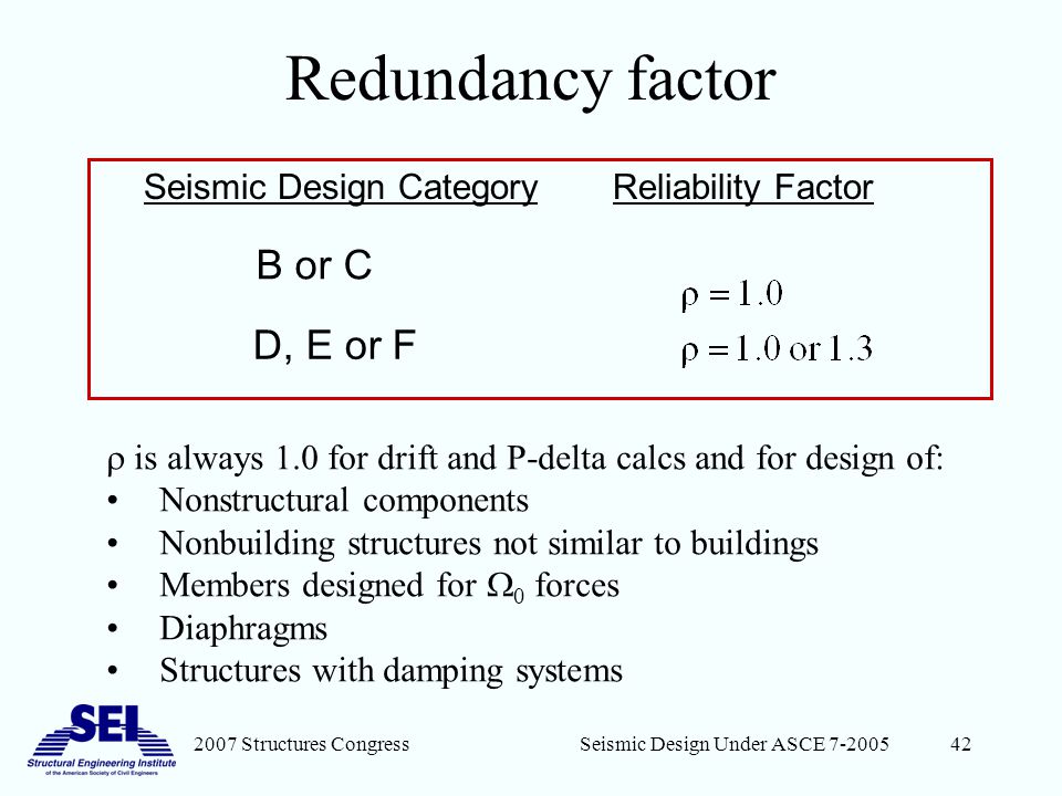
When there is no redundancy the seismic forces must be increased by 30. Also known as the reliability factor the redundancy factor ρ introduces a multiplier to increase thedesign horizontal force being considered for a structural element. Redundancy Factor 33-42 Seismic Load Combinations 43-46.
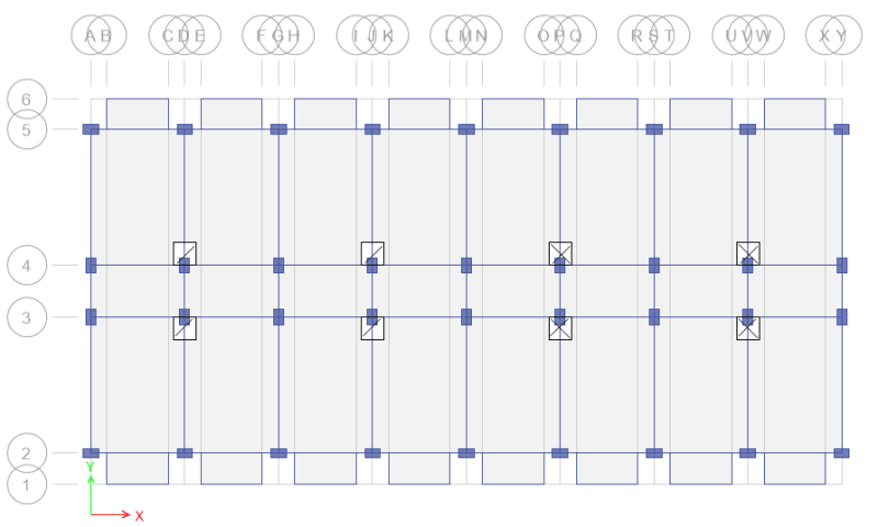
Use of an importance factor greater than one is intended to provide for a lower inelastic demand on a. If a structure is regular in plan and there are at least 2 bays of seismic force resisting perimeter framing on each side of the structure in each. Assessment of redundancy factors for the seismic design of special moment resisting reinforced concrete frames.
Seismic Design Category B or C. In ASCE 7 it is a factor applied to seismic loads when certain low-redundancy conditions are met. Introduction of the redundancy coefficient into the building code was a direct reaction of the observation of structures damaged by the 1994 Northridge earthquake and the resulting.
Requires Calculations Redundancy Factor ρ ASCE 7-16 12342 ρ 10 or 13 ρ 13 unless ONE of the following conditions is met. A state of redundancy in astructural system can be attained by allowing several load path options for the lateral loads actingon the structure. Of redundancy over the structural strength through the input kinetic energy of seismic excitation.
Instructional Material Complementing FEMA 451 Design Examples Seismic Load Analysis 9 - 4 Load Analysis Procedure Continued 9. The response modification coefficient R is part of a concept where an elastic design may be performed but with due consideration of the overstrength and ductility inherent in the lateral force resisting system. H E EρQ 1 where Q E is defined as the effects of horizontal seismic forces from V total design lateral force or shear at the base or F p the seismic force acting on a component of a structure.
For structures assigned to SDC D E and F ρ13 unless one of the following two conditions is met then ρ10 12342. International Building Code 2006 Edition. Examine system for configuration irregularities 10Determine diaphragm flexibility flexible semi-rigid rigid 11Determine redundancy factor ρ 12Determine lateral force analysis procedure 13Compute lateral loads.
For structures in Seismic Design Categories SDCs D E and F the redundancy factor is 13 but may be reduced to 10 if it passes either a configuration test or a calculation test. Draft redundancy factor which varies as a function of the number of the vertical lines. U en y E r E 2 where Eu is the total seismic energy for the lifespan of the structure until collapse and Ey is the seismic energy up to the first yielding.
Latin American Journal of Solids and Structures 12. Wang and Wen 2000 studied a 3-D building model under seismic loadings. TehMightyEngineer Structural 15 Jan 15 1649.
ACI 318-11 Appendix D actually revised this requirement in two ways to make it align with the ASCE 7-10 seismic load combinations with overstrength factor. The most important parameters influencing such factor are the ductility the lateral stability and the in-plane redundancy. 2330-2350 a reliabilityredundancy factor for the seismic design of buildings ϱ was first introduced in NEHRP 97 UBC 1997 and IBC 2000 IBC-2006 2006.

Scielo Brasil Redundancy Factors For The Seismic Design Of Ductile Reinforced Concrete Chevron Braced Frames Redundancy Factors For The Seismic Design Of Ductile Reinforced Concrete Chevron Braced Frames

Redundancy Factors Proposed By Atc 19 1995 Download Scientific Diagram
Scielo Brasil Redundancy Factors For The Seismic Design Of Ductile Reinforced Concrete Chevron Braced Frames Redundancy Factors For The Seismic Design Of Ductile Reinforced Concrete Chevron Braced Frames

Scielo Brasil Redundancy Factors For The Seismic Design Of Ductile Reinforced Concrete Chevron Braced Frames Redundancy Factors For The Seismic Design Of Ductile Reinforced Concrete Chevron Braced Frames

Scielo Brasil Assessment Of Redundancy Factors For The Seismic Design Of Special Moment Resisting Reinforced Concrete Frames Assessment Of Redundancy Factors For The Seismic Design Of Special Moment Resisting Reinforced

Scielo Brasil Assessment Of Redundancy Factors For The Seismic Design Of Special Moment Resisting Reinforced Concrete Frames Assessment Of Redundancy Factors For The Seismic Design Of Special Moment Resisting Reinforced
2007 Structures Congress Selected New Provisions Of Asce Sei Ppt Download

Scielo Brasil Redundancy Factors For The Seismic Design Of Ductile Reinforced Concrete Chevron Braced Frames Redundancy Factors For The Seismic Design Of Ductile Reinforced Concrete Chevron Braced Frames
0 comments
Post a Comment