How to Design and Debug a Phase-Locked Loop PLL Circuit. ZSet the loop bandwidth to one-tenth of input frequency.

Rf Phase Lock Loop Pll And Synthesizer Key Parameters Youtube
Determining the design of a PLL usually means also determining the design of the loop filter which affects aspects of loop performance.
. Many of the basic concepts and design equations are given in this application note. All key non-linear effects that can impact PLL performance can be simulated including phase noise Fractional-N spurs and anti-backlash pulse. Learn more about PLL design with the PLL Performance Simulation and Design Handbook.
The ADIsimPLL design tool is a comprehensive and easy to use PLL synthesizer design and simulation tool. The program calculates component values based on system performance specifications provided by the user. Low Power RF PLL-Synthesizer Operating From a Single Cell Battery Reference Design.
It supports integer or fractional PLL modes plots open and closed loop gain and phase margin. It is the most comprehensive PLL Synthesizer design and simulation tool available today. Content is provided as is by TI and community contributors and does not constitute TI specifications.
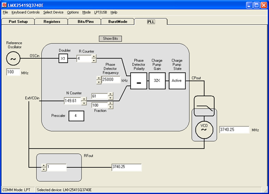
Typical PLL system block diagram. Once the loop is locked the phase. Download the LMX2592 data sheet.
All key nonlinear effects that can impact PLL performance can be simulated including phase noise fractional-N spurs and anti-backlash pulse. Our portfolio helps you select the right IC design the application BOM. Learn more about TIs PLL portfolio.
I am struggling with the PLL phase noise simulation with clock design tool for LMK04828. ADI HMC PLL Design Software Download. Thank you for your interest in the PLL Design Software.
Simply download the file setup_pll_designexe run it in Windows ie double click on it in Windows Explorer and then follow the setup instructions. We provide a wide variety of design tools models and simulators to help you with the board design process. View datasheets for the LMX2592 and LMX2582.
The Loop Calculator tool calculates component values for PLL loop filter design. ADIsimPLL removes at least one iteration from the design process thereby speeding the design- to-market. Designing and debugging a phase-locked loop PLL circuit can be complicated unless engineers have a deep understanding of PLL theory and a logical development processThis article presents a simplified methodology for PLL design and provides an.
RF PLLs synthesizers LMX1204 128-GHz RF buffer multiplier and divider with JESD204BC SYSREF support and phase synchronization LMX2430 30-GHz08-GHz PLLatinum dual high frequency synthesizer for RF personal communications LMX2433 36-GHz17-GHz PLLatinum dual high frequency synthesizer for RF personal communications LMX2434 50-GHz25-GHz. By Ray Sun Download PDF Introduction. Learn how to calculate your gamma and PLL values quickly with the PLLatinum simulator tool.
A PLL system consists of a stable and clean reference clock a PLL device and a loop filter followed by a voltage-controlled oscillator VCO. Tool Basics The PLL Design Assistant provides a graphical user interface methodology to the design of phase. Click on the PllDesign icon created during the installation process.
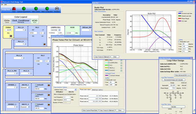
A Phase-Locked Loop PLL is a closed-loop circuit that compares its output phase with the phase of an incoming reference signal and adjusts itself until both are aligned ie the PLL outputs phase is locked to that of the input reference. The basic design equations for the passive loop filter is in National Semiconductors Application Note AN-1001 An Analysis and Performance Evaluation of a Passive Filter Design Technique for Charge Pump Phased Locked Loops. The Clock Design Tool software helps with part selection loop filter design and simulation of timing device solutions.
Figure 6 shows that it takes 514 microseconds to change the frequency from 1675 MHz to 1735 MHz 1000 Hz. I simulate the PLL1 phase noise curves by typing below in clock design tool. The datasheet says the PN1Hz and PN10KHz of PLL1 as below.
The simulated results for the design PLL at450 MHz indicates good. When you enter desired output frequencies and a reference frequency optional the tool provides TI devices to meet the specified requirements divider values and a recommended loop filter to minimize jitter. The PLL Design Software is a powerful PLL design tool that enables users to accurately model and analyze performance of all Analog Devices HMC PLLs.
Simulations performed include all key non-linear effects that are significant in affecting PLL performance. A Phase-Locked Loop PLL is a closed-loop circuit. Loop BW 25ω n for ζ 1 zSelect a charge pump current tens of microamps to some milliamps.
Fully compatible with prior releases the ADIsimPLL design tool eliminates time. Read the PLL Performance Simulation and Design Handbook Simulate your design using TIs Clocks and Synthesizers TICS Pro Software and PLL Simulator. File directory in the PLL Design Modelszip file attached into the same directory where Hittite_PLL_Design_Toolexe is located which is.
Loop Filter Calculation Tool is a program that calculates component values for PLL loop filter design. This is achieved using a software phased-locked loop PLL. The ADIsimPLL design tool is a comprehensive and easy-to-use PLL synthesizer design and simulation tool.
The tool calculates component values based on system performance specifications provided by the user. The earlier version of HMC PLL Design V11 required MatLabs MCR V711 which was not readily available from MathWorks. Browse our portfolio of diverse selection tools calculators simulation tools and model libraries that aid the entire PCB design process.
Find advice on understanding datasheet phase noise specifications of PLLs. In this paper selection and design for Second order and third orderPLL suggested using MATLAB Simulink as a simulation tool. Hop Time PLL Synthesizer Practical Considerations Capacitors An important part of the Loop Filter design is the use of components that will not degrade the.
Select Advanced in the Feature Level check box to unlock the gamma optimization parameter option. Grid connected applications require an accurate estimate of the grid angle to feed power synchronously to the grid. To run the program.
Kindly can you please take some time to check if there any errors during my simulation. PLL BasicsLoop Filter Design 4 Fujitsu Microelectronics Inc. PLL Design Procedure zDesign VCO for frequency range of interest and obtain K VCO.
PLL Design Software Version 11.

Lmk04806beval Evaluation Board Ti Com
Clockdesigntool Application Software Framework Ti Com

Why Component Integration Matters For Space Based Pll Synthesizers Electronic Products
Codeloader Ide Configuration Compiler Or Debugger Ti Com

Phase Lock Loop Pll Bandwidth Design Part 1 Ti Com Video

Webench Tools Lmx2572lp Ti Pll Platinum Sim Clock Timing Forum Clock Timing Ti E2e Support Forums

Pllatinumsim Sw Application Software Framework Ti Com

Clock Design Tool Loop Filter Design Youtube
0 comments
Post a Comment